Feature Enhancements: |
|
| Export SVG Hyperlinks in a project are supported in the SVG Export format. |
|
| Fluids The density of the fluid is taken into account in Rotodynamic Pumps. The motion control valve supports the different models. |
|
| Electrotechnical Added the Wind Turbine component. « Irradiance generator »: Improved calculation of the end of cycle time. « Wind generator » : End of cycle signal correction. |
 |
| General Handling time optimization in large files. Optimization of the time to generate the BOM. Display of an hourglass for longer operations. |
|
Customer issues fixed: Mechanism Manager
Fixed a problem encountered when linking 4 cylinders. |
|
| PDF Export
Fixed an issue with the reports. |
|
| Video recording Fixed a jump problem when editing properties during an asynchronous recording. |
|
Assembly
|
|
| Revision history Sort by functional revision date in the history. |
|
What's New in Automation Studio 6.4
Service Releases
Feature Enhancements: |
|
| Service Release The SR3 update was developed to resolve an issue with an update for Microsoft® Access®. |
|
The new database management system in version SR3 allows the complete detachment of Automation Studio™ from Microsoft® Access® for catalogues, project files and all the databases required for its operation. |
|
Although the installation is optional, the benefits of this service release are noticeable for customers who have experienced problems with previous versions: |
|
|
|
|
This new release requires to update each file that was created in an older version of the software. It will be done automatically when you open a file in Automation Studio™. To convert your projects, catalogues and custom libraries all at once to the latest version, we have developed this File Converter application. To convert your projects generated with version 5.7 to the new format, you must first save them with a version prior to version 6.4 SR3. |
|
|
|
|
Feature Enhancements: |
|
FLUIDS |
|
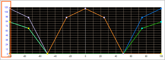
| Directional valves Less points will be created when the flow curves are generated in directional valves; axes are not scaled anymore. |
 |
| Motopumps Motopumps get two sets of efficiency curves, whether they work in motor mode or in pump mode. |
 |
| Pneumatic cylinder Addition of a pneumatic cylinder with diaphragm and of a multiport pneumatic cylinder configurator.. |
 |
ELECTROTEHNICAL |
|
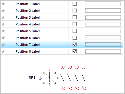
| Switches Addition of displaying the "Position" options on switches. |
 |
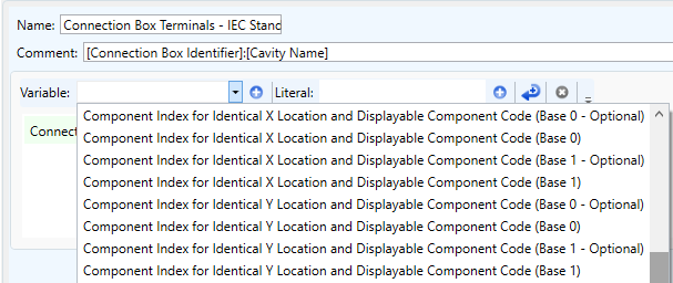
| New numbering options Addition of numbering options for wires and components. |
 |
| Installation and circuit Addition of option for displaying location variables. |
 |
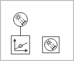
| Renewable energy Addition of renewable energy components, such as the Photovoltaic cell and the Photovoltaic generator. |
 |
GENERAL |
|
| OPC Addition of the OPC UA Client (communication protocol). Addition of co-simulation scaling variables and synchronous control device. |
 |
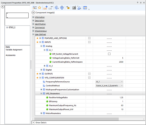
| Enumerations and Variables structures The Custom Component enhancement allows the use of enumerations and variables structures to set up the generated component. The Block Diagram (Math) Workshop can be used to model the behaviours of the Custom Component. It is then easy to create advanced components such as Electrical Variable Frequency Drives. |
 |
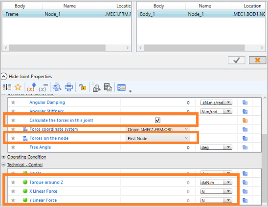
| Mechanism Manager Possibility to access the forces variables used in the Mechanism Manager. |
 |
| Bellow Actuator Bellow Actuator can be used in the Mechanism Manager and it also has been added into the sizing sheet. |
|
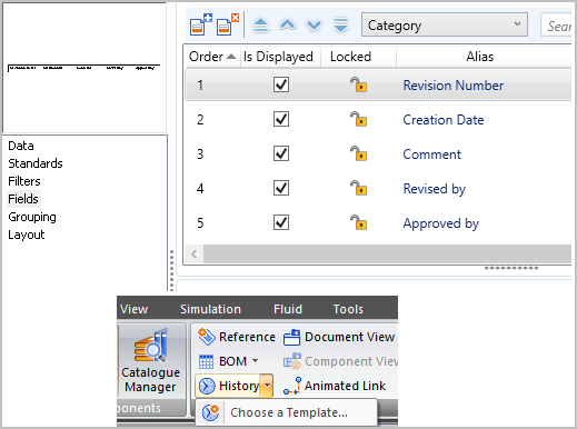
| History The history of schematics or project revisions has been redesigned according to the report concept. |
 |
| Addition of map locator’s options. | 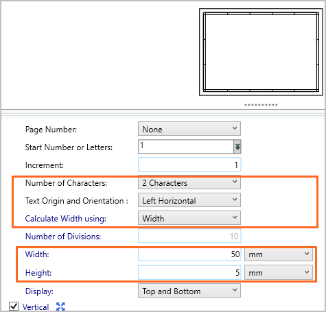 |
Customer issues fixed: Project management
|
|
Hydraulic directional valves
|
|
| Pressure regulator Pressure initialization in the pressure regulator, when the simulation is started from a data acquisition, was corrected. |
|
| Cylinder The cylinder model has been improved to extend the range of possible dimensions. |
|
Hydraulic lines
|
|
| Accumulator The model of the accumulators has been improved to extend the range of usage. |
|
| Timers Fixed the reset of the pneumatic timers. |
|
| Mechanism The computation convergence has been improved for the mechanisms using mechanically linked cylinders. |
|
| Electrical The compatibilities between electro-potentiometers and Panel Layout workshop have been extended. |
|
| Components help The help for the operating conditions of components as well as their properties has been improved. The conditions of usage are more detailed. |
|
| Main Library Hiding the LSIS workshop in the main library configuration is now possible. |
|
| Catalogues Fixed unlocking properties for some of the manufacturers products used in a schematic. |
|
| Export PDF format Issue with PDF export was fixed. |
|
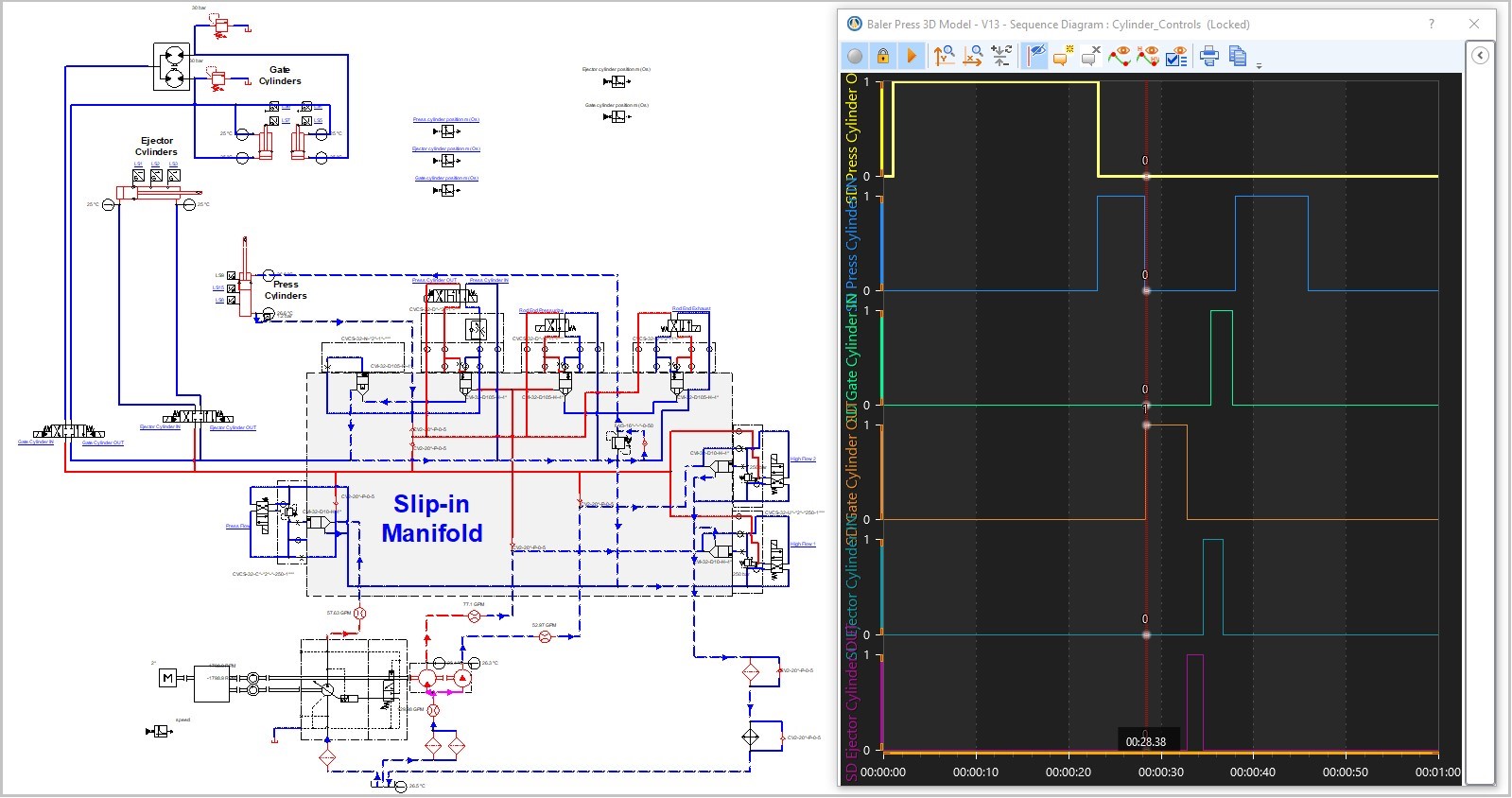
| Sequence Diagram The Sequence Diagram is a visual intuitive tool that allows you to create operation sequences quickly without needing a specific control language or an electrical control circuit. |
 |
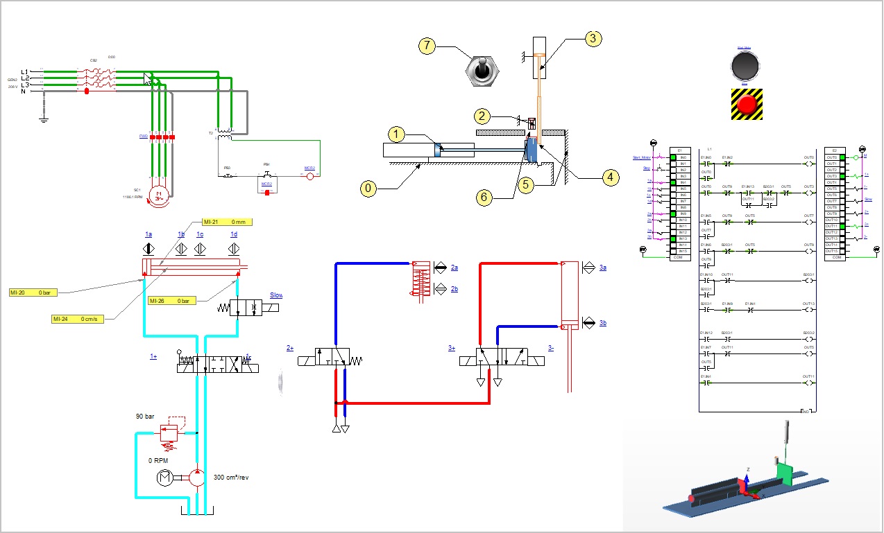
| Embedded Views This function fulfills the training and technical publication requirements. It allows adding views from all different technologies into a single document. For example, it is possible to embed into a single page, a partial view of a hydraulic circuit, a 3D view and a partial view of a GRAFCET, etc. |
 |
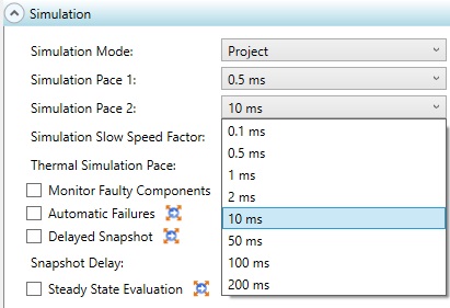
| Additional simulation paces New, up to 200ms, simulation steps are available providing lighter computing demands during simulation. This feature is particularly useful for large projects. |
 |
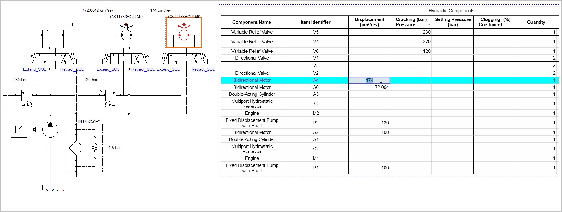
| New BOM Completely redesigned the document’s BOM (bill of materials). The new version brings great flexibility in customizing the displayed information as well as its appearance. You can also now edit components’ properties directly from the BOM. |
 |
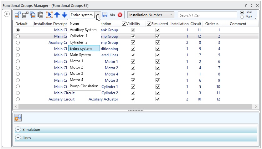
| Functional groups Following ISO 1219-2’s recommendation, you can now subdivide any system into functional groups. You can then efficiently design, simulate, validate and visualize your system function-by-function and quickly compare the different options. |
 |
| Optimisation in loading, saving and closing projects. Significantly improved performance specifically when opening and closing large projects. |
|
| Mechanical links The Mechanical links allows to easily connect different technologies as electrical and fluid power. |
|
| Project components update Automation Studio™ 6.4 will identify improved components. Depending on the type of improvement, you can update the project’s components either manually or automatically. |
|
| Visibility option for connection port names You may now display either all of the connection port names or only the desired one when inserting components from the main library. |
|
| Display of mechanical ports A new option exists to display the different types of ports on the components: Mechanical, Electrical and Fluids. |
|
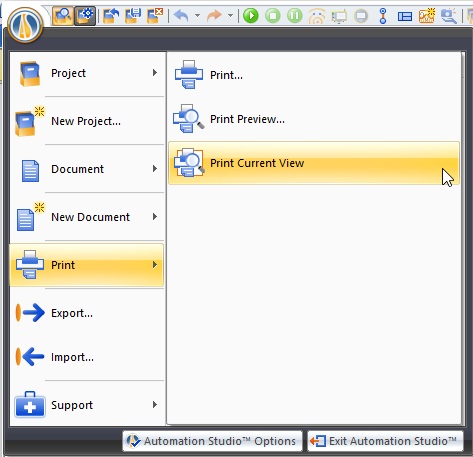
| Print curent view Implemented the option to print the current view. |
 |
| Mechanical links The mechanical links allow for an easy connection between components from different technologies, such as electrical and fluid power. |
|
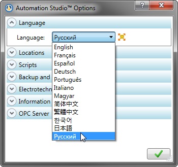
| New language interface Automation Studio’s interface is now available in Russian. |
 |
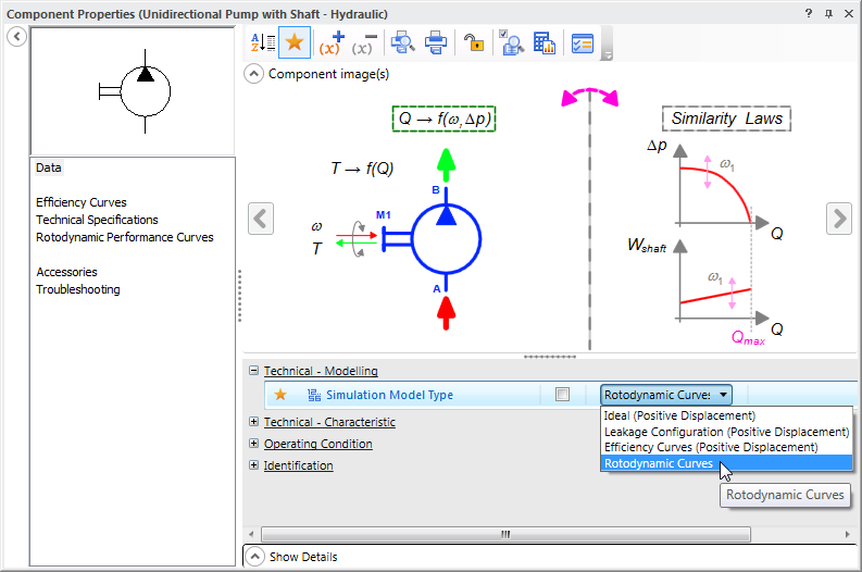
| Centrifugal pump Added the option to manage the rotodynamic in order to support the centrifugal pump models. |
 |
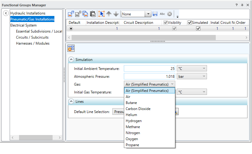
| Compressible Fluids The simulation of new compressible fluids such as azote, hydrogen, helium, methane and propane are now available in the Pneumatics Workshop. |
 |
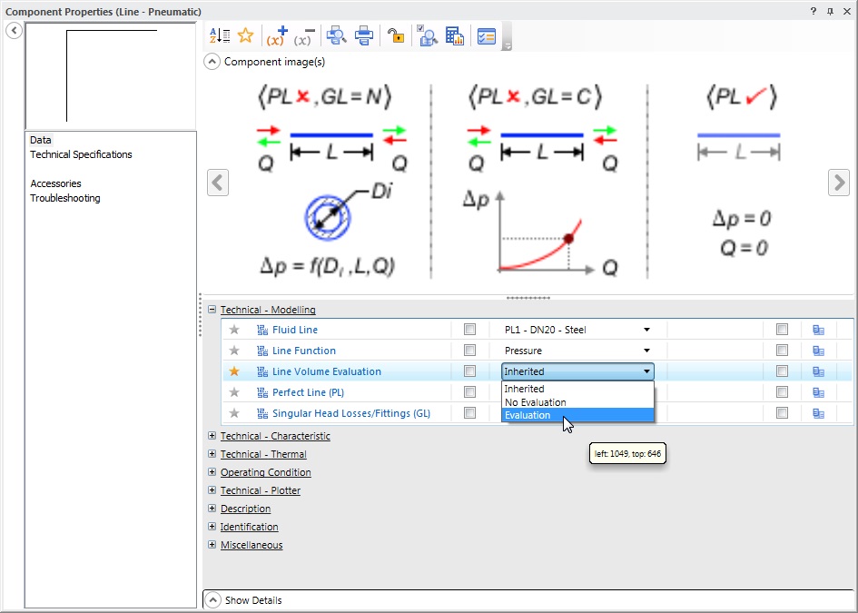
| Volume in pneumatic lines Implemented the option to account for volumes in compressible fluid pipes. This increases the propagation precision of the working pressure. |
 |
| Mechanics on electrotechnical components Electrotechnical asynchronous machines, stepper motors, permanent magnet DC motors are now equipped with mechanical connection ports. Position and speed sensors, as well as shafts and mechanical links, can be easily connected to machines facilitating controls and linking to other modules. |
|
| Electric machines The Electrotechnical Module is now equipped with a new induction motor and a permanent magnet DC motor. |
|
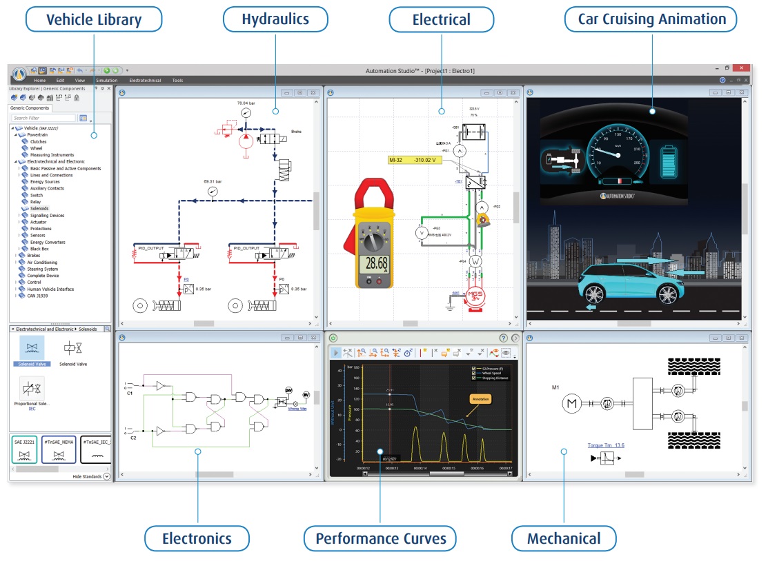
| Automotive library All components needed for automotive project development are now grouped into a specific library, which includes the electrotechnical components, under SAE standard. |
 |
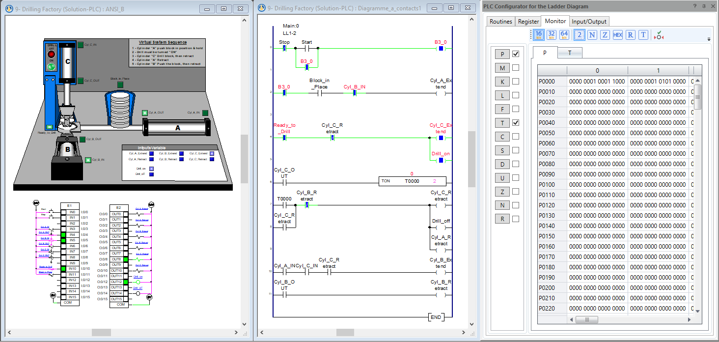
| Ladder Diagram LSIS Implementation of the new Ladder diagram module based on LSIS PLC specifications. |
 |